
From Laboratory to Industrial Scale Processing, we have the right wiped film, short path distillation system for your operation. With decades of experience and hundreds of units operating in facilities in multiple countries, we understand customer needs and are dedicated to delivering the highest quality, turnkey, high vacuum short path distillers available. Complete with a number of different regulatory packages depending on your facility requirements; including Peer Review, Installation Qualification (IQ), Operational Qualification (OQ), and Performance Qualification (PQ) Documents.
Separation Science, Click Here To Learn More About High Vacuum Distillation
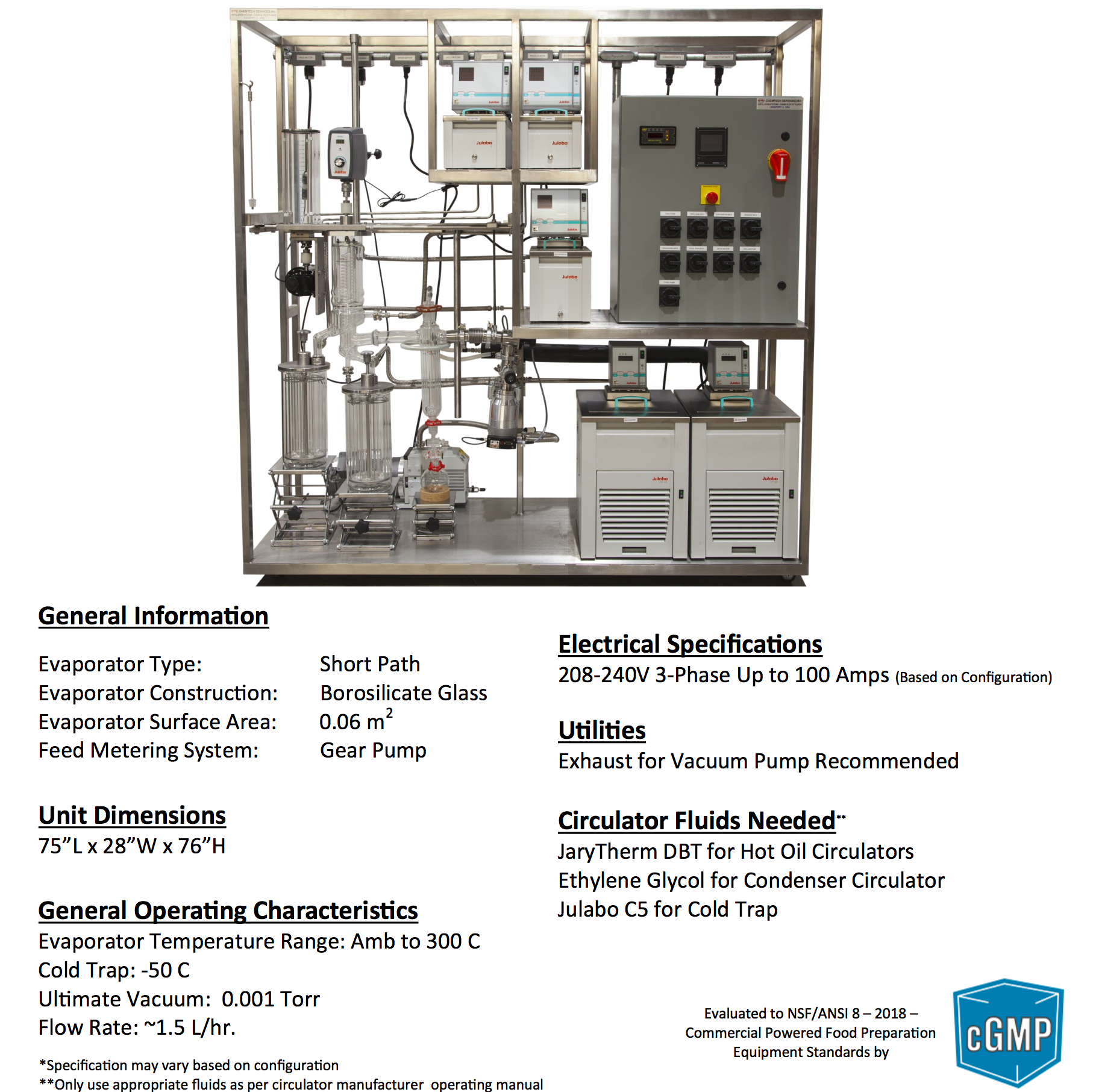
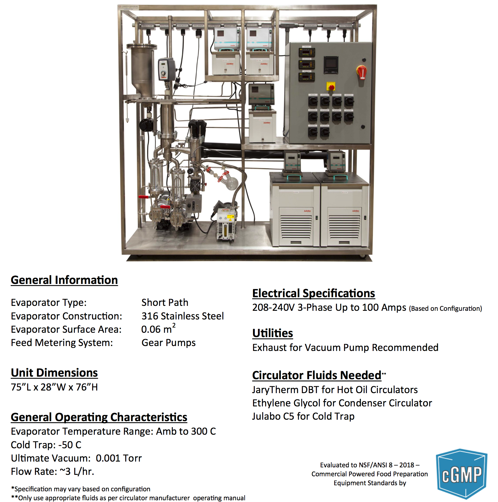
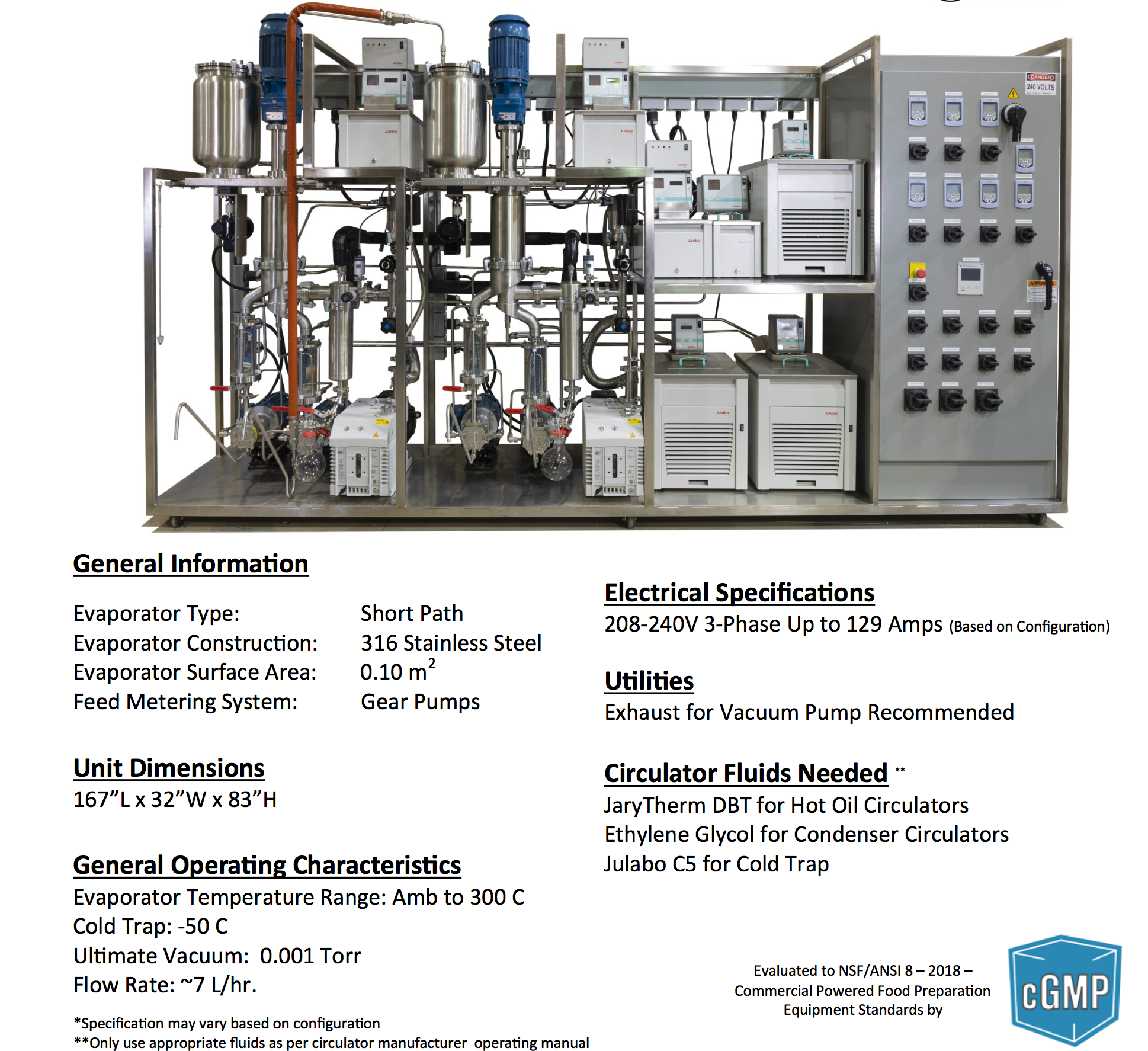
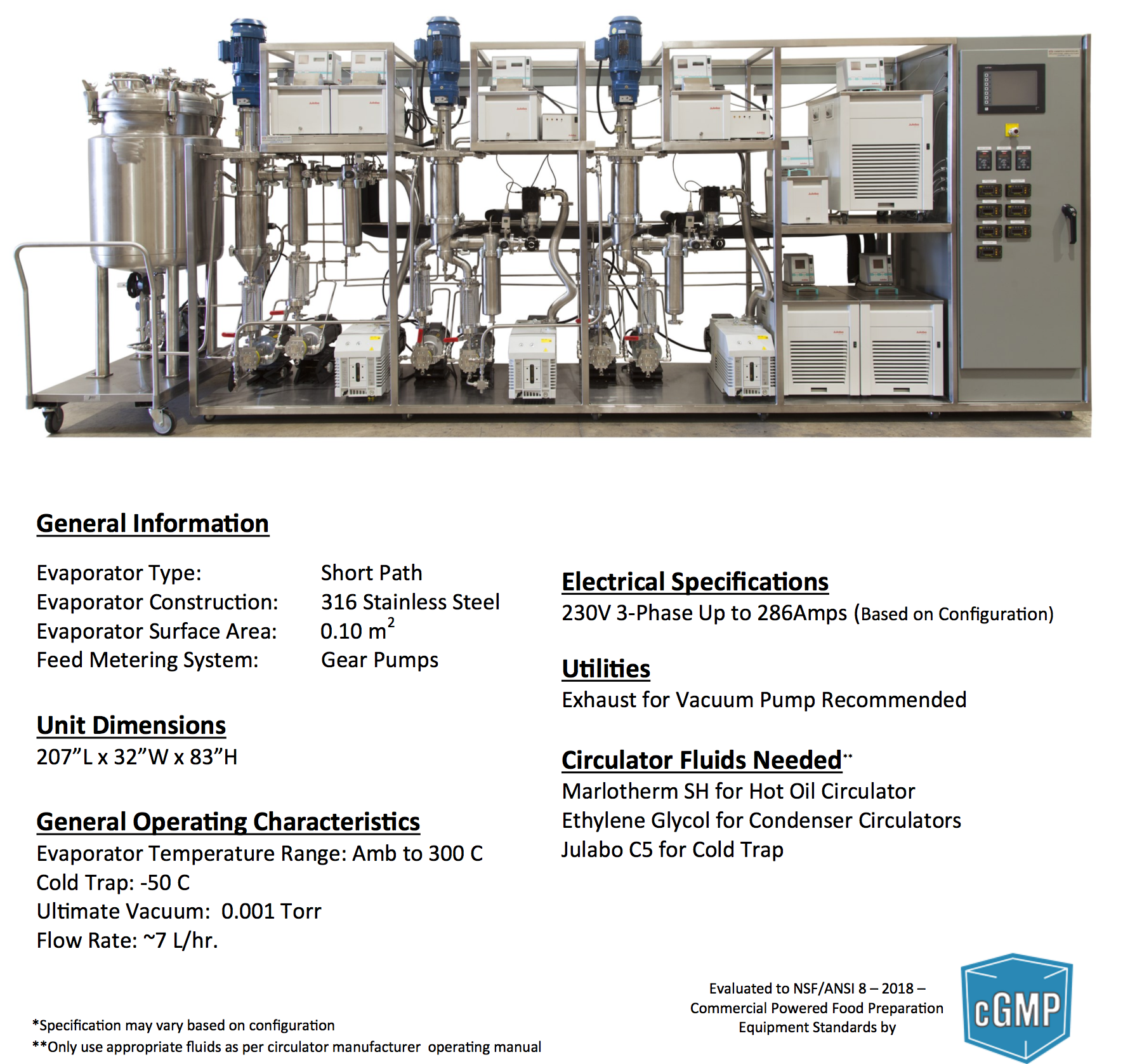
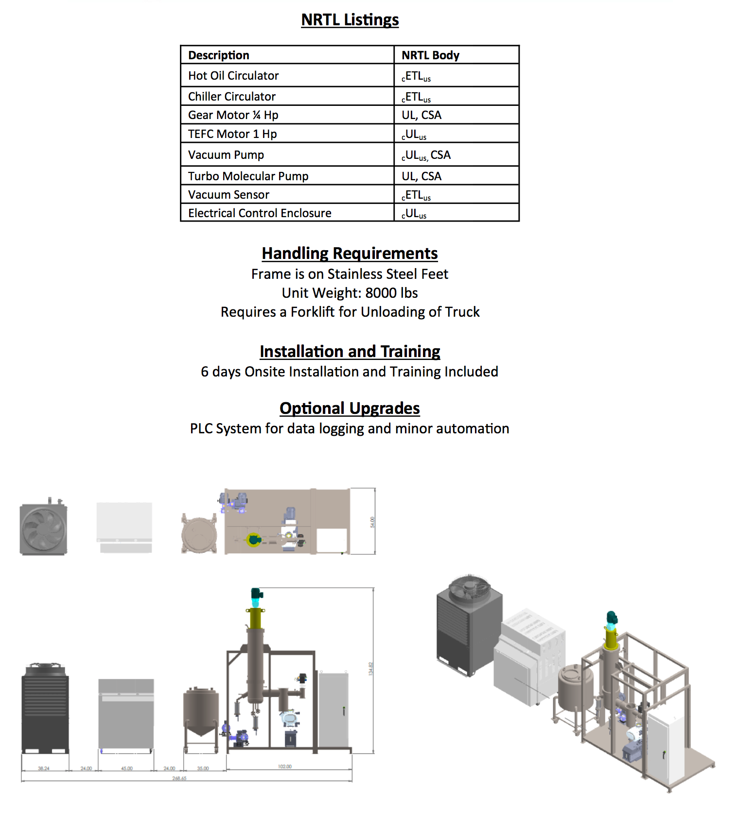
2024 Short Path Distillation Standard System
KDL-4 Bench Model

KDL-4

KDL-5

KDL-6

KDT-6
Dual Stage KDT-6


KD10

Dual Stage KD10
Triple Stage KD10

KD30


Dual Stage KD30
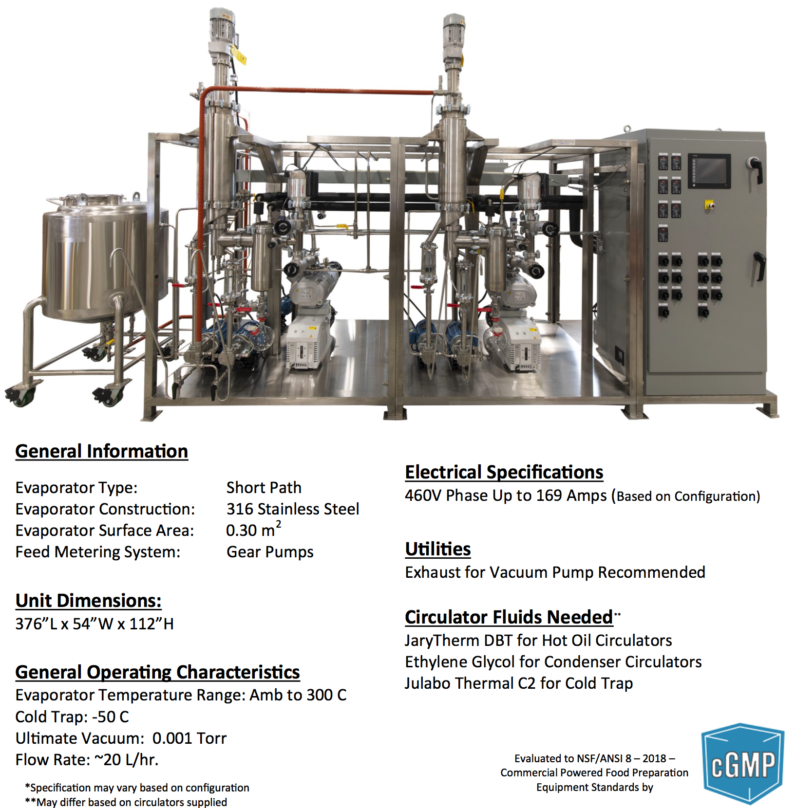

Triple Stage KD30

KD75

Dual Stage KD75


SYSTEM CONFIGURATION
Wiped Film / Rolled Film (RFL) and Short Path (KDL) Distillation system designed for Laboratory distillation applications are available with a wide ranging list of features and options which can significantly affect the operating capabilities of the unit. In this brochure, a number of the basic systems configurations and potential options will be reviewed. However, our experience with Short Path Distillation Division has been most RFL or KDL Systems sold in recent years have been customized to some extent based on the end user’s specific distillation requirements. Some of the basic elements and potential for customization are discussed below.
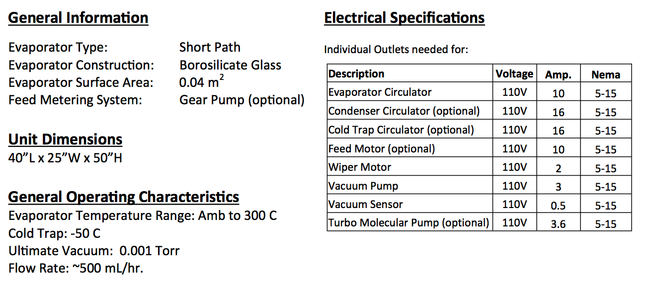
Basic Evaporator Sizing:
The primary and most important component used in any Wiped Film or Short Path Distillation system is the actual evaporator (sometimes referred to as the distillator). As indicated previously, laboratory systems typically utilize evaporators ranging in size from 0.010 m2 to 0.100 m2. Other vessels configured in a system, such as: feed tank, receivers and cold traps, are sized based on the customer requirements. The sizing of these vessels is usually dependent on feed sample quantity requirement and duration of distillation run. For example, collection vessel sizes are as small as 0.50 liter and as large as 5.0 liters are common in laboratory units.
Feed Vessel Specifications:
A variety of standard feed vessels are available for Laboratory Distillation systems, and non-standard vessels may be available depending on requirements. Generally the material of construction used in the feed vessel will be the same as the evaporator although there are occasional exceptions to this rule. Several operating parameters should be considered when selecting a feed vessel:
Capacity: Typically 2, 5, 10 liter vessels are available on standard unit mini 5 – KDT6
Heating Requirement: Jacketed and non-jacketed vessels available
Metering System:
Two basic metering systems are available: (a) Vacuum feed with a metering valve between the feed vessel and evaporator; (b) Metering pump which is typically mounted on the evaporator support plate and integrated with the feed vessel
Hardware Support Systems:
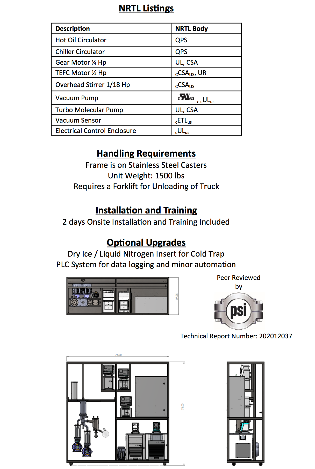
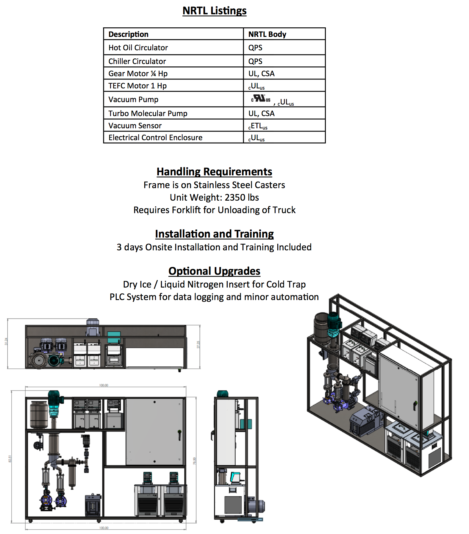
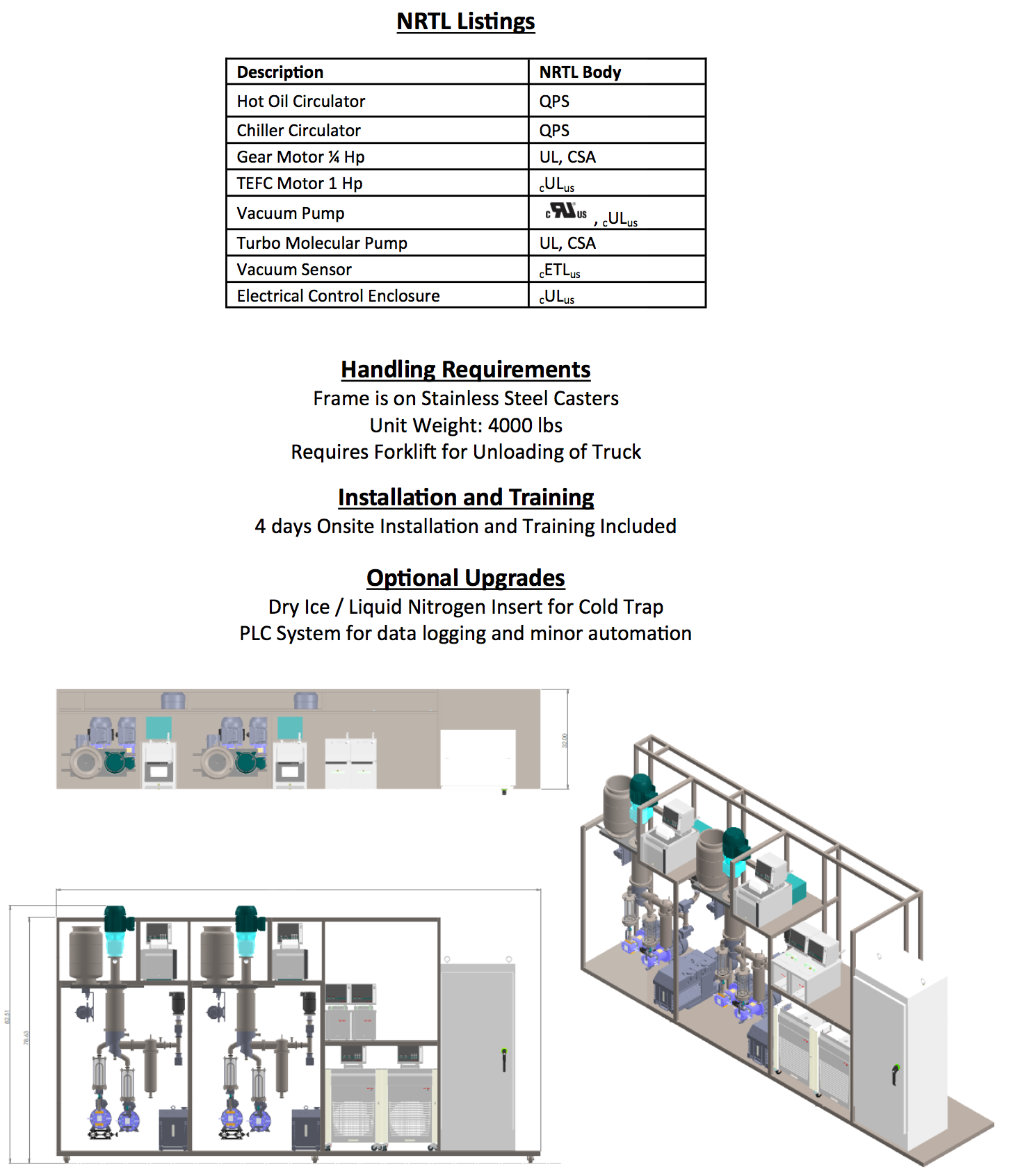
The “Basic System” for RFL or KDL Distillation equipment (for countertop applications) utilizes ring stands for support with the ancillary equipment (vacuum pumps and circulators) positioned strategically on the lab countertop to support the operation of the Evaporator. Many customers prefer more positive support ranging from a small stainless steel cart to larger welded frames which may support a single evaporator or multiple evaporators (staged in series) and the required ancillary equipment including circulators. Welded frames normally utilize two (2) alternative materials of construction: (1) Welded Unistrut (carbon steel) coated with two- component epoxy in a color of choice; or (2) 304 Stainless Steel Square-tube (uncoated). Both frame styles have an integrated drip-pan for spill control and special features such as exhaust hoods are available as options. Frame mounted systems also include castors and levelers for convenient movement and leveling where multiple laboratory locations may be desirable.
Temperature Control Circulators:
Heating and Cooling Circulators are used to maintain the temperature in the critical zones associated with this system. Generally, we consider five independent zones as requiring temperature control: (1) Feed System; (2) Evaporator Heating Jacket; (3) Evaporator Residue Jacket; (4) Condensing Vessel or Coil; and (5) the Cold Trap. The ability to control the evaporating temperature and the condensing temperature suggests the circulators which service these zones are the most critical (re: zones 2 and 4 in the illustration). The necessity to use circulators for the feed and residue portions of the evaporator is a function of the viscosity of the material being distilled. Generally, when the viscosity of the materials (feed, distillate or residue) exceeds 1000 cps, circulators are recommended. Circulators range in operating characteristics and selecting the correct circulation is based upon available voltage (e.g., 240 VAC @ 60Hz), power requirements related to heating and cooling (e.g., 2.5 kW heating with 800 Watts cooling), and control interface (e.g., simple PID for local control, or PID with RS232 interface for remote control). Typically, zones 1 – 3 described above are services with “heating only circulators” while zone 4 would normally be a “heating & cooling circulator: and zone 5 a “cooling only circulator.” Most heating circulators have a maximum temperature of 300°C which typically accommodates 80% of the distillation applications, but if temperatures above 300°C are required, a high temperature circulator with a sealed oil reservoir is available, which can reach 350°C with a 6kW heating capacity. If a circulator is used to service a closed loop Cold Trap (as an alternative to a cryogenic cold trap using dry ice or liquid nitrogen) the maximum temperature requirement is typically -40°C, although dual stage chillers are available which reach temperatures as low as -90°C.
Vacuum System:
The most typical vacuum configuration for laboratory applications utilizes a rotary vane pump as the primary source of vacuum (or backing pump) which is subsequently “boosted” (or amplified) in Short Path Systems with an oil diffusion pump to attain a 0.001 mbar dry vacuum. Alternative vacuum systems might use high capacity (CFM flow rates) rotary vane pumps or small dry pumps in special cases. In addition to the pumps used to attain vacuum, a manifold system connected to the cold trap may contains bleed valves (e.g., for N2 addition), isolation valves and a port for mounting the vacuum sensor (pirani gauge)
Product Collection Vessels:
The intended functionality of the Distillation System will influence the selection of the product (distillate and residue) collection method. The simplest collection method utilizes borosilicate glass flasks which may range in size from 500 ml to 5.0 liters. The flasks are interfaced with the distillate and residue nozzles on the evaporator (or evaporator and external condenser in a conventional WFE) and would normally include an isolation valve between the evaporator (condenser) nozzles which allow the operator to empty the flask when the evaporator is under vacuum. More sophisticated distillation units might use a “Rotary Carousel Sampling System” which contains six (6) individual 150 ml sample tubes housed in a four (4) liter glass vacuum vessel. This Rotary Carousel allows the operator to obtain multiple distillate and residue product samples during the distillation process which samples can also be generated at different AEBP. The Rotary Carousel is a popular option with research organizations in their efforts to optimize process conditions through multiple sampling for subsequent analytical evaluation. The size of the distillation samples required by a customer might also dictate the necessity for optimizing the process dynamics of the Distillation System by adding vacuum rated, gear metering pumps to the distillate and residue discharge nozzles. Gear pumps are especially useful if the materials being distilled are highly viscous in nature, where positive displacement pumps will facilitate higher processing rates. The use of vacuum rated, gear pumps typically allows discharge directly to containers at atmospheric conditions. Gear pumps are a common feature in distillation systems utilizing stainless steel evaporator systems where high process rates (compared to glass evaporators) are possible through improved heat transfer. Gear pumps are available with (or without) an integral hot oil jacket for high viscosity of high melt point products which must be processed at higher discharge temperatures
Electrical Controls & Power Distribution:
As suggested in the preceding sections, a functional distillation system includes many elements which require electrical power to operate. Summarizing, power will be required to operate: (a) Evaporator wiper system; (b) temperature control circulators: (c) vacuum pumps; (d) product feed or discharge pumps (if applicable); and (e) instrumentation (e.g., vacuum sensors, data loggers, PLC, etc.). Simple bench top systems can be assembled on a laboratory bench with a simple power strip providing electrical utility for all the components. However, in the case of frame mounted systems which typically utilize a multitude of electrical components it is more common practice to supply an electrical panel mounted on the frame for power and instrument signal distribution to the electrical components. The size of the electrical panel is typically influenced by the complexity of the distillation system (how many electrical components), control instrumentation requirements, and customer site prerequisites (e.g., NEC code and specific customer requests). Therefore, a laboratory distillation system which includes an electrical control panel may have an enclosure which ranges in size from a 12” by 12” panel to a full size 36” by 72” electrical & instrumentation enclosure.
In addition to considering the electrical enclosure and power distribution requirements, consideration should be given to the level of instrumentation and control required for the application under consideration. In the case of bench top systems, all switches and controllers (primarily PID’s integrated into temperature circulators) are local to the ancillary component (such as wiper system motor, PID controller on hot oil or glycol circulators). In more complex frame mounted systems instrumentation and controls are located in the electrical enclosure. Basic controls might include panel mounted power switched for ancillary components and digital displays for temperature and vacuum readings. More sophisticated instrumentation and control would include Data Logging devices or PLC controls to allow unattended operation of the distillation system. Data Logging devices facilitate accurate record keeping which can be downloaded using a USB port and thumb drive, while PLC systems include the Data Logging function but also control the distillation based upon parameters programmed by the operator (e.g., AEBP requirement). The disadvantage of the more sophisticated Data Logging or PLC system is the higher price requirement as electronic interfaces are added to the hardware package.
Processing rates are based on the system’s capacity to feed crude into the evaporator: average runtimes, yields, and final potency are dependent on input material, generally base on extracted biomass material anatomy, quality, and processing protocol.Check with your local Fire Marshall, Federal, and Industry Regulators for additional information.Shipping dimensions and weights may vary.All specification subject to change.Stock photo may not represent actual system as sold to date.Product performance, specification, and packages subject to change.Customized systems may have longer lead times. Equipment manufactured to be used only for legal purposes. Ask us about discounted Used and Refurbished systems sold “as is”.
All ORDERS ARE SUBJECT TO HELDERPAD’S STANDARD TERMS AND CONDITIONS OF SALE AGREEMENT.
Please contact a member of the Helderpad team for more information: (564) 218-8398 or inquiries@helderpad.com
